
Multi Jet Fusion is a powder based additive manufacturing (3D printing) technology created by HP. We currently have the largest fleet of MJF printers in the UK & offer the greatest range of MJF materials.
There are a number of factors to consider regarding part quality, price & mechanical properties when using MJF:
Quality
Material Selection
Minimum Wall Thickness
Maximum Size & Split Parts
Wall Thickness & Hollow Parts
Lattices & Structures
Pipes & Internal Channels
Multiple Bodies/Shells & Moving Parts
Threads & Threaded Inserts
Porosity & Water Resistance
Automated Finishing Processes
Full Finishing Service
Tolerance
Ordering
File Size, Formats & Resolution
Revision Control & Issue Numbers
Pricing & Lead Time

Material Selection
We offer 3 different MJF materials each with it’s own use cases. In short PA12 is the most commonly used material in MJF (and also SLS) as it has a good balance of properties & economics. PA11 is used when a tougher more ductile material is needed, also it is a biopolymer (created from plant based oils). Finally TPU is mostly used for flexible products & also functions well in applications where impact protection is needed.
Full data-sheets can be found here, below is a brief summary of the main differences:

Minimum Wall Thickness
Minimum feature size depends on the type of design feature. While extremely thin features may form we can’t guarantee they won’t break during the powder removal stages.

Short walls that are sufficiently supported can be as thin as 0.5mm. Be mindful that this is extremely fragile and should only be used in short sections (image).
In most cases a minimum thickness of 1mm is safer, and 2mm+ will make the part significantly stronger.

For cantilevers HP recommend that if the thickness is less than 1mm then the aspect ratio (Length ÷ Width) should be less than 1.
In real terms this means that any cantilever thinner than 1mm must have a length shorter than it’s width.
For thicker cantilevers there are no set rules, but consider adding ribs or other supporting geometry to maximise strength.

Sprues & wire frame designs are naturally fragile.
At 1.2 mm thickness you can print up to 7 mm long, 2.0 mm wires can get up to 30 mm long. Anything longer than this is extremely fragile and likely to break.
Additionally avoid fragile design practices such as joining multiple large sections together with thin sprues. This has a high change of breakage.
Maximum Size & Split Parts
While the total build volume of an MJF machine is 380 X 284 X 380 mm, we need to allow a 4mm gap on all sides giving a usable volume of 372 x 276 x 372mm. For anything larger than this the part needs to be split & joined back together once printed. We normally offer this free of charge.
Parts that have been joined back together will have a visible join line. This line can be hidden with filler, sanding & paint which is an additional service that we offer (See Full Finishing Section).

There are a number of different types of joint that can be used including most wood-working joints.
If we need to split your part we will choose the most suitable for your specific geometry to optimise joint strength & ease of assembly.
If you have specific requirements, for example water resistance, please let us know so we can take it into consideration when splitting your part.
Wall Thickness & Hollow Parts
For parts with sections over 10mm thick to print accurately we typically hollow them with a 4mm thick wall section.
If the part has no powder drain holes the inside section will remain filled with un-fused powder. This trapped powder will never be visible unless the part is cut or broken in half.

Powder drain holes can be added to a design when it is beneficial for the powder to be removed. For example if the part has been hollowed for weight reduction.
We recommend these holes are a minimum of Ø5mm but generally the bigger the better.
A cap with a 0.15mm clearance can be printed & bonded in after powder has been cleared.

Adding multiple drain holes will allow us to fully remove the powder as beads can be blasted through the part.
Consider adding one each end of the part allowing a clear path for air to blast the glass beads through the part, clearing out all of the powder.

If strength is required internal structures can be added to the part inside the hollow. Unlike other processes this adds no extra time to the print. (See Lattices & Structures section)
Lattices & Structures
One of the advantages of MJF over SLS is the ability to print intricate lattices without adding extra build time (print time).
With such lattices the weight of a part can be reduced whilst retaining most of it’s strength.
We can add lattices to parts using our range of professional CAD packages, including SOLIDWORKS, nTopology, Materialise Magics or Rhinoceros.

When printing with our flexible TPU material lattices can be used to control the flexibility of a part.
Areas that need to be stiffer can be printed with a thicker lattice structure than areas that need to be more flexible.

Similar considerations regarding minimum feature size need to be made to lattices (See minimum feature size section).
If the lattice is internally within a part, especially if fully enclosed, the chance of breakage is considerably lower as it is protected. In these cases going as low as 0.8mm is feasible, although it will offer little structural advantage.

Pipes & Internal Channels
Printing internal channels & pipes directly into the part is often used to reduce the number of components & steps in an assembly.
If internal channels are used, the design phase must consider powder removal, or the channel may be partially or fully blocked.
For these channels to be cleared please ensure they are at least 5mm in diameter. Larger diameters are even better.

Aim to reduce sharp corners & kinks in the channel. Consider that un-used powder must be removed with a tool during blasting. If the tool can’t get around the corner then we cant fully ensure that the void is clear of powder.
These two examples connect the same start & end-point together, but the top one is much more likely to be free of powder.

Similarly try to link internal chambers to the outside world through pipes that follow a spline path.
If it is critical to have no powder in the chamber, the best solution is to print the part with a large access hole that gets permanently closed once powder has been removed.


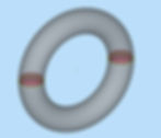
Multiple Bodies/Shells & Moving Parts
Since MJF is self-supporting it is possible to print ‘moving parts’ without requiring assembly.
This is most commonly seen in:
Hinges
Sliding parts
Chainmail / ‘3D Printed Fabric’

A clearance must exist between the two bodies to ensure they do not fuse together.
This clearance will depend on the exact design, thicker parts will need a greater clearance gap as there is more heat energy.
For our ‘MultiHinge’ sample (image), when built in Nylon PA12, a 0.3mm clearance is sufficient as it has thin walls around the hinge.

Below is a rule of thumb based on HP’s recommendations & our observations. Ultimately every design is different and testing will be required, but this is a good place to start:

Threads & Threaded Inserts
Brass threaded inserts are the best way to add a thread to an MJF printed part. These are pressed in with heat after the print has finished.
We can order in most types of threaded insert and carry stock of standard unheaded inserts from RS Components:

If threads printed directly into the part are required it is best to print a standard hole & cut the thread into the part with a tap.
Use the standard tapped hole drill size charts provided by ISO or whichever standard the thread requires.

Porosity & Water Resistance
MJF Printed parts are naturally porous, but if the part’s wall thickness is great enough it can meet IP (Ingress Protection) ratings and be considered water resistant.
IP ratings are specific to the design of the part & vary depending on the geometry.
As a rule of thumb wall sections of 4mm are usually enough to be considered ‘water proof’.
A more detailed answer is provided by HP here:

According to research conducted by AMT the vapour smoothing process decreases porosity as it decreases the surface energy. This means that water is more likely to ‘bead’ rather than soak in.
This study can be read in detail here:

Automated Finishing Processes
DYEMANSION DM60
Our automated finishing processes are a great way of altering & improving the surface finish of a whole batch of parts at once.
This means it is much more economical than our full finishing service which is more labour intensive (See full finishing section).

The DYEMANSION DM60 dye machine is used to change the colour of MJF 3D printed parts. Unlike painting it adds no extra thickness & requires much less labour.
Black dye is charged as 10% on top of the part price, where additional colours are £100 per batch (batch size depends on part size).
AMT PostPro
AMT PostPro vapour smoothing creates a glossy smooth finish, sealing the part removing its porosity (See previous section).
During AMT smoothing the part must be suspended from a hook.
Please ensure the design of the part includes a feature to hang the part from, this could be:
Holes
Lattices
Sacrificial sprue with a hoop
For PA12 & PA11 sprues should be Ø2mm.
For TPU sprues should be Ø4mm.


Full Finishing Service
We can paint MJF parts to almost any finish & colour, but we will need to know what RAL paint-code you require before we can quote this. More information on RAL paint-codes can be found here:


Tolerance
Expected tolerance for MJF is +/- 0.3mm, although it is typically better. We can reduce this tolerance by first running a test print of your part, taking measurements, & then adjusting the scaling to account for shrinkage. We can also offer 3D scanning & deviation analysis. Every geometry shrinks differently hence the need to print a test of your specific part. If this is required please let us know as it will need to be quoted for as an additional service.

Any part that has been split & re-assembled can’t have its tolerance controlled as closely without creating a specific jig for the part. Again this is an additional service that we can quote for.
File Size, Formats & Resolution
We accept most 3D CAD formats. If your file has been created in a solid or surface modelling software (e.g. SOLIDWORKS) and hasn’t yet been tessellated (converted to triangles) we recommend using STEP format. If your file has already been converted to triangles we recommend STL format.

Using STEP files allows us to control the tessellation which removes most problems with file sizes that are too large or resolutions that are too low.
If your file is already tessellated sending an STL file is the best option.
Bare in mind that files with an excessively high resolution will be too large to handle & have diminishing returns in accuracy as they reach the limitations of the technology.
A rule of thumb is that files over 70MB are usually unnecessary for single parts.

Before sending your files please check for the following:
- Missing faces
- Extra parts that you don’t intend to print
- Intersecting surfaces
- Surfaces with no thickness
While we can repair most simple errors, it is impossible to accurately re-create some missing geometry. Additionally we may need to charge extra if the time required to fully repair is too long.

Revision Control & Issue Numbers
Naturally when dealing with both prototypes & batch production designs often get updated.
It is best practice to keep a revision or issue number in the file name which you update when the design has changed.
Please ensure you supply the correct file for printing before confirming the order as it is not uncommon for us to start printing as soon as the order is confirmed.

Pricing & Lead Time
We currently offer two lead time / price options depending on your needs.

Please be aware that some services, materials & large orders are only offered in a longer lead time as we need to allow time to complete them to our high quality standards.